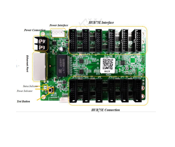
1 Product Overview
Product Introduction
H12T is a receiving card that fully researched and developed by Zhanxin; it adopted 12x HUB75E interfaces; it can supports the maximum 24 groups of the parallel connection data;the maximum loading capacity could reach up to 512*640 pixels; with strong processing ability, supper reliability and high competitive price.
Application Scenarios
It could be widely used for high-end LED display area that requires high standards; and has significant advantages in application scenarios such as led rental display, TV Broadcast, LED display for respectable Event,High-end project,etc.
2Function Introduction
Displaying Effect
|
It supports pixel level brightness and Chroma Calibration |
Using it with the Zhanxin Calibration Software to calibrate each one
of the pixels on its brightness and Chroma. It can effectively eliminate the Chromatic aberration so as to enhance its consistency of the brightness and Chroma to a high level and result in a better displayed effects. |
|
Multiple Solutions of the Displayed Effects are Supported |
Using it with Zhanxin AutoLED Software, the Refresh and
Grey Scale performances are able to take the precedence over other settings. |
| The Images on the led screen can be rotated 90 degree in a factor of multiple times |
Using it with Zhanxin AutoLED Software. |
| The images can be zoomed in or out | Using it with Zhanxin AutoLED |
Enhanced Operability:
|
The Receiving Card is Supported to detect its own Sequence number |
Using the Network Port testing function on Zhanxin AutoLED Software, the receiving card serial number and the Network Port Information will be displayed on the target cabinet. Users will be able to get to know the locations of the receiving cards as well as its . Connection diagram. |
|
Data Port User-Defined is supported |
Using it with the Zhanxin AutoLED Software, you can detect and edit the output data of the receiving cards. |
| To build up a complicated cabinet is
supported |
On AutoLED Software, there is an‘Advanced Setting’, from here you can quickly arrange or structure the |
| modules at your option. | |
|
To structure a complicated Led Screen is supported |
On AutoLED Software, there is a “Complicated Led Screen Connection”, from here you can quickly arrange or structure the cabinet modules on your option. |
Hardware Stability
|
Ethernet Cable Backup(Hot Backup) |
The main cable will be having the loop connection. If there’s one cable breaks then still there will have another one to make sure the led display work properly. |
| Dual receiving cards backup is supported( Dual Circuit backup design)
Customized :when the main working receiving card fails, the other one (backup) will take its job to keep the led display working properly. |
Smart Software and Hardware Stability
| The receiving card can read the configuration data back from
where it has been stored |
You will be able to do this on Zhaxin AutoLED Software. |
|
It supports to detect the error rates of the network cable |
On the Zhanxin AutoLED Software, you can detect the network cable
connectivity in real time to tell the condition of the network cables, so that you can get rid of any errors immediately. |
|
Communication Monitoring Function |
On Zhanxin AutoLED Software, you can monitor the Working Status of
the receiving cards in real time. |
|
Dual Power Supplies Backup is supported |
2 Power Supplies can be connected simultaneously and the working status can be detected. Whenever there’s a power
supply failure, it can be detected, the system then will automatically decrease the brightness of the led screen so that it can still keep working properly |
| It supports to detect the
voltage(customized) |
It will detects the voltage status of the receiving cards. |
| It supports to detect the
temperature(customized) |
The operating temperature of the receiving cards could be detected. |
| It supports to detect the power
status(customized) |
The power status of the power supplies could be detected. |
| Supports pixel-by-pixel correction | Support 40 parallel data |
| Unique arbitrary frequency doubling technology, mobile phone photos without line scanning | Support external LCD module |
| Support mapping function | Support temperature and voltage monitoring function |
| Supports all PWM and general purpose chips. | Support FLASH management of light board. |
3Product Parameters
| RGB Parallel | Data Ports/Interface s/QTY | Driver IC | The Maximum Loading Capacity(Pixel
s) |
Loading Capacity After lightness Calibrating
(Pixels) |
Loading Capacity after Color Calibrating(Pixels) |
| 40 Groups | HUB75E/12
RJ45/2 |
Conventional | 512*320 | 512*256 | 256*320 |
| PWM | 512*640 | 512*256 | 256*320 |
Basic Parameters
| Single Network Port Cascading Quantity | Scan line supports 2 network ports |
| ≤1000PCS | 1-128 Scan |
Hardware Introduction
Output Port Definition
Port Definition of the 24 Groups of parallel connection data
| JP4 | JP3 | JP2 | JP1 | |||||||||
| R7 | 1 | R5 | 1 | R3 | 1 | R1 | 1 | |||||
| G7 | 2 | G5 | 2 | G3 | 2 | G1 | 2 | |||||
| B7 | 3 | B5 | 3 | B3 | 3 | B1 | 3 | |||||
| WE4 | 4 | WE3 | 4 | WE2 | 4 | WE1 | 4 | |||||
| R8 | 5 | R6 | 5 | R4 | 5 | R2 | 5 | |||||
| G8 | 6 | G6 | 6 | G4 | 6 | G2 | 6 | |||||
| B8 | 7 | B6 | 7 | B4 | 7 | B2 | 7 | |||||
| HE2 | 8 | HE2 | 8 | HE1 | 8 | HE1 | 8 | |||||
| HA2 | 9 | HA2 | 9 | HA1 | 9 | HA1 | 9 | |||||
| HB2 | 10 | HB2 | 10 | HB1 | 10 | HB1 | 10 | |||||
| HC2 | 11 | HC2 | 11 | HC1 | 11 | HC1 | 11 | |||||
| HD2 | 12 | HD2 | 12 | HD1 | 12 | HD1 | 12 | |||||
| CLK4 | 13 | CLK3 | 13 | CLK2 | 13 | CLK1 | 13 | |||||
| LAT 4 | 14 | LAT 3 | 14 | LAT 2 | 14 | LAT 1 | 14 | |||||
| OE4 | 15 | OE3 | 15 | OE2 | 15 | OE1 | 15 | |||||
| GND | 16 | GND | 16 | GND | 16 | GND | 16 | |||||
| CON16
JP8 |
CON16
JP7 |
CON16
JP6 |
CON16
JP5 |
||||||||||
| R15 | 1 | R13 | 1 | R11 | 1 | R9 | 1 | ||||||
| G15 | 2 | G13 | 2 | G11 | 2 | G9 | 2 | ||||||
| B15 | 3 | B13 | 3 | B11 | 3 | B9 | 3 | ||||||
| WE8 | 4 | WE7 | 4 | WE6 | 4 | WE5 | 4 | ||||||
| R16 | 5 | R14 | 5 | R12 | 5 | R10 | 5 | ||||||
| G16 | 6 | G14 | 6 | G12 | 6 | G10 | 6 | ||||||
| B16 | 7 | B14 | 7 | B12 | 7 | B10 | 7 | ||||||
| HE4 | 8 | HE4 | 8 | HE3 | 8 | HE3 | 8 | ||||||
| HA4 | 9 | HA4 | 9 | HA3 | 9 | HA3 | 9 | ||||||
| HB4 | 10 | HB4 | 10 | HB3 | 10 | HB3 | 10 | ||||||
| HC4 | 11 | HC4 | 11 | HC3 | 11 | HC3 | 11 | ||||||
| HD4 | 12 | HD4 | 12 | HD3 | 12 | HD3 | 12 | ||||||
| CLK8 | 13 | CLK7 | 13 | CLK6 | 13 | CLK5 | 13 | ||||||
| LAT 8 | 14 | LAT 7 | 14 | LAT 6 | 14 | LAT 5 | 14 | ||||||
| OE8 | 15 | OE7 | 15 | OE6 | 15 | OE5 | 15 | ||||||
| GND | 16 | GND | 16 | GND | 16 | GND | 16 | ||||||
| CON16
JP9 |
CON16
JP10 |
CON16
JP11 |
CON16
JP12 |
||||||||||
| R17 | 1 | R19 | 1 | R21 | 1 | R23 | 1 | ||||||
| G17 | 2 | G19 | 2 | G21 | 2 | G23 | 2 | ||||||
| B17 | 3 | B19 | 3 | B21 | 3 | B23 | 3 | ||||||
| WE9 | 4 | WE10 | 4 | WE11 | 4 | WE12 | 4 | ||||||
| R18 | 5 | R20 | 5 | R22 | 5 | R24 | 5 | ||||||
| G18 | 6 | G20 | 6 | G22 | 6 | G24 | 6 | ||||||
| B18 | 7 | B20 | 7 | B22 | 7 | B24 | 7 | ||||||
| HE5 | 8 | HE5 | 8 | HE6 | 8 | HE6 | 8 | ||||||
| HA5 | 9 | HA5 | 9 | HA6 | 9 | HA6 | 9 | ||||||
| HB5 | 10 | HB5 | 10 | HB6 | 10 | HB6 | 10 | ||||||
| HC5 | 11 | HC5 | 11 | HC6 | 11 | HC6 | 11 | ||||||
| HD5 | 12 | HD5 | 12 | HD6 | 12 | HD6 | 12 | ||||||
| CLK9 | 13 | CLK10 | 13 | CLK11 | 13 | CLK12 | 13 | ||||||
| LAT 9 | 14 | LAT 10 | 14 | LAT 11 | 14 | LAT 12 | 14 | ||||||
| OE9 | 15 | OE10 | 15 | OE11 | 15 | OE12 | 15 | ||||||
| GND | 16 | GND | 16 | GND | 16 | GND | 16 | ||||||
| CON16 | CON16 | CON16 | CON16 | ||||||||||
JP1-JP12 PIN Definition:
| Illustration | Definition | PIN# | PIN# | Definition | Illustration |
|
RGB Data Output |
R | 1 | 2 | G | RGB Data Output |
| B | 3 | 4 | GND | GND | |
| R | 5 | 6 | G | RGB Data Output | |
| B | 7 | 8 | HE | Line Decoding Signal | |
| Line Decoding Signal | HA | 9 | 10 | HB | |
| HC | 11 | 12 | HD | ||
| Shift Clock Output | CLK | 13 | 14 | LAT | Latch Signal |
| Display Enable(Remarks 1) | OE | 15 | 16 | GND | GND |
Remarks 1: Pin # 15 is the display enable pin. And When using the PWM chip it will be the GCLK Signal.
J11 Pin Definition:
| Definition | PIN# | PIN# | Definition |
| +5V | 1 | 2 | GND |
| FLS_CS | 3 | 4 | FLS_DO |
| FLS_CLK | 5 | 6 | FLS_DI |
| PROGRAM_B | 7 | 8 | mCONF_DONE |
| GND | 9 | 10 | +5V |
J12 Indicator PIN Definition:
| PIN# | 1 | 2 | 3 | 4 | 5 |
| Definition | GND/KEY- | KEY+ | LEDR- | VCC/LED+ | LEDG- |
J14 Socket PIN Definition:
| PIN# | 1 | 2 | 3 | 4 |
| Definition | VCC | VCC | GND | GND |
Indicator Illustration
| Indicator | Position | Status | Illustration |
|
Status Indicator (Green) |
U1 |
Flickering Slowly at
a constant |
The receiving card is working properly, The Ethernet Cable Connection is fine, No DVI
Signal Input |
| Flickering
Fast at a constant |
The receiving card is working properly, The Ethernet Cable Connection is fine, with DVI
Signal Input |
||
| It goes out | No Gigabit Ethernet Signal | ||
| Fast
Flickering 3 Tunes |
The receiving card is working properly, The
Ethernet Cable Loop Connection is fine, DVI Signal Input |
||
| Status Indicator |
U3 |
Long
Lasting On |
Power is On |
Dimensions
4Product Specifications
Specifications
|
Electric Parameters |
Input Voltage | DC3.5-5.5V |
| Rated Current | 0.6A | |
| Rated Power | 3W | |
| Operating Environment | Operating Temperature | -30℃ – 70℃ |
| Operating Humidity | 10%RH-90%RH | |
| Storage Environment | Temperature | -40℃~125℃ |
| Dimensions | 144.02mmX91.19mm | |
| Net Weight | 100.8g | |
| Certifications | It conforms to RoHS and CE-EMC standards. | |
Precautions
- The testing (debugging) and installation should be done by the qualified professionals
- Anti-Static, Water-Proof and Dust-Proof Required

